
I used to judge these sensors the easy way. Compare the bias stability number, check the temperature range, shortlist the part, move on. After enough time around downhole tools, I stopped doing that. In this environment, the number on the datasheet is the parteasiest that is easiestthing to get right, and the least informative once the tool is downhole.
Downhole, there is no GPS. At several thousand metres, the only way to know where the bottom-hole assembly is pointing is to build the answer from measurements inside the tool itself. Magnetometers are cheap and straightforward, but inside casing or in magnetically noisy formations, their output cannot be trusted on its own. That is where a gyro earns its keep.
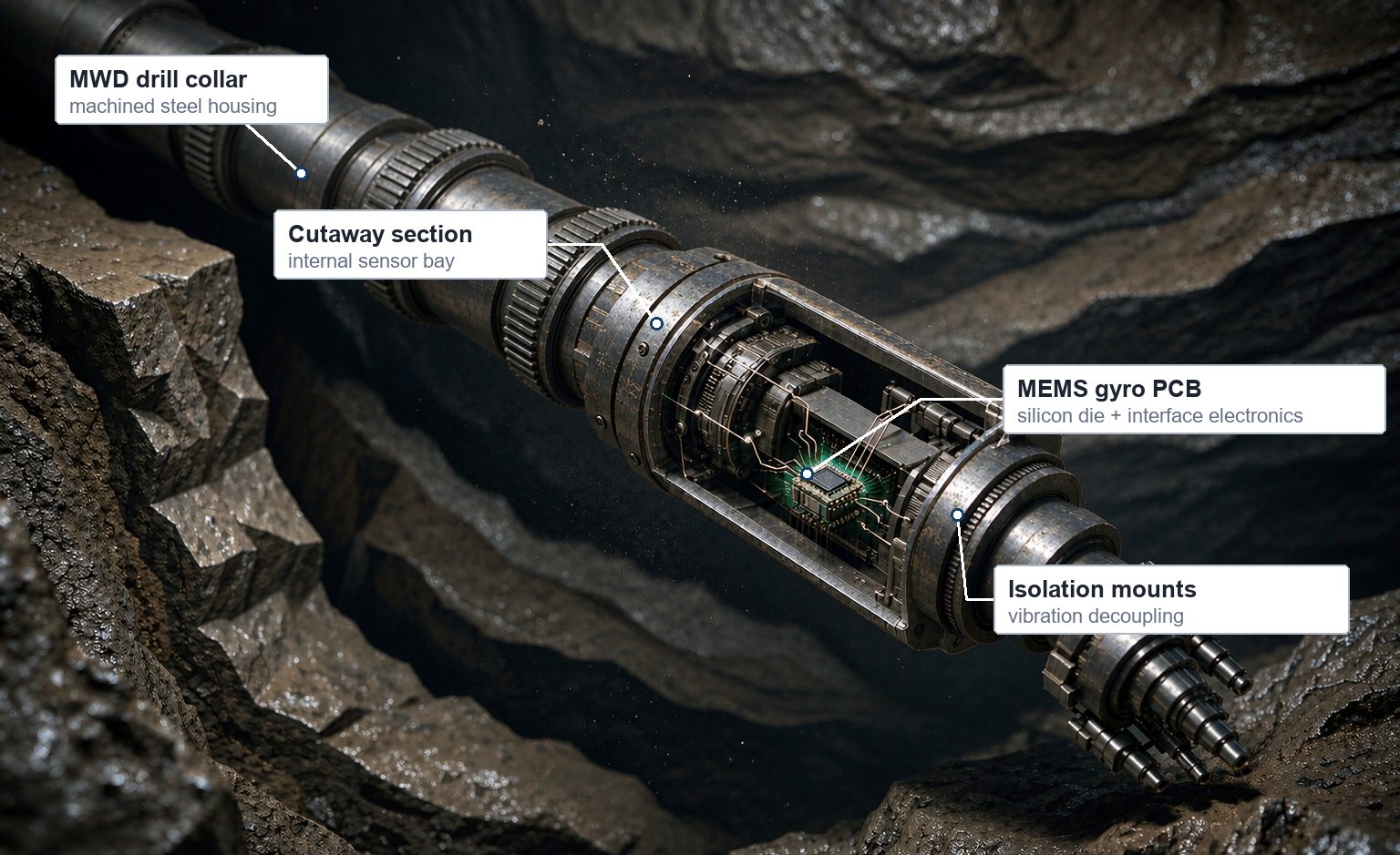
Figure 1. A MEMS gyroscope is packaged inside a drill collar that sees heat, mud, shock and broadband vibration.
What the gyro actually measures
This distinction matters. A gyroscope does not hand you azimuth. It measures angular rate aroundabout three axes. Combine those rates with accelerometers in an inertial measurement unit, integrate through an attitude algorithm, and you get inclination, azimuth and tool face angle. Azimuth is a different story: it comes from an initial north-seeking alignment, in which the gyro senses Earth rotation to establish true north, and is then propagated by integration. Skip that alignment and the tool knows how it is tilted, but not which way it faces.
Tool face is the one I pay closest attention to. In sliding mode, that is the number the directional driller uses to decide which way the bit is pushed. A small angular error at the sensor becomes a steering error at the bit, and nobody sees it until the survey comes back.
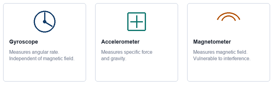
Figure 2. Three sensors, three physical quantities. Reliable tool attitude comes from how they are combined.
Why MEMS, and not a better gyro?
Fiber-opticFibre-optic and mechanical gyros can deliver better bias stability. That is not the question. The question is what fits inside an MWD or LWD collar, survives 150–175 °C, tolerates shock and vibration, draws modest power, and costs little enough to run on every job.
MEMS sits in that narrow window. The die is only a few millimetres across, the power budget is small, and the package can be ruggedised without turning the tool into a laboratory instrument. It is not a universal replacement for high-grade gyros. It is the option that makes inertial attitude measurement possible in tools where a FOG or a mechanical gyro simply does not fit.
|
Sensor / technology |
Size & power |
Magnetic independence |
Shock & vibration |
Practical role downhole |
|
MEMS gyro |
Excellent |
Yes |
Good if packaged well |
Mainstream attitude sensing where size, cost and power are constrained. |
|
Mechanical gyro |
Bulky / high power |
Yes |
Moderate |
High-accuracy survey tools and special applications, now largely legacy hardware. |
|
Fiber-opticFibre-optic gyro |
Larger / moderate power |
Yes |
Good |
Premium navigation and high-performance survey while drilling. |
|
Fluxgate magnetometer |
Excellent |
No |
Good |
Azimuth in non-magnetic environments; unreliable near casing. |
Table 1. Qualitative comparison for downhole use.
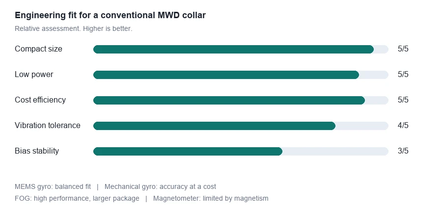
Figure 3. MEMS does not win on every metric. It wins on the combination that matters inside a real tool.
Where the engineering really happens
Two gyros with similar room-temperature bias specifications can behave very differently once the tool is downhole. At 150 °C and above, with broadband vibration from the drill string, the bias term drifts. Because attitude is integrated over time, a small rate error becomes a growing angle error. The longer the interval, the worse it gets.
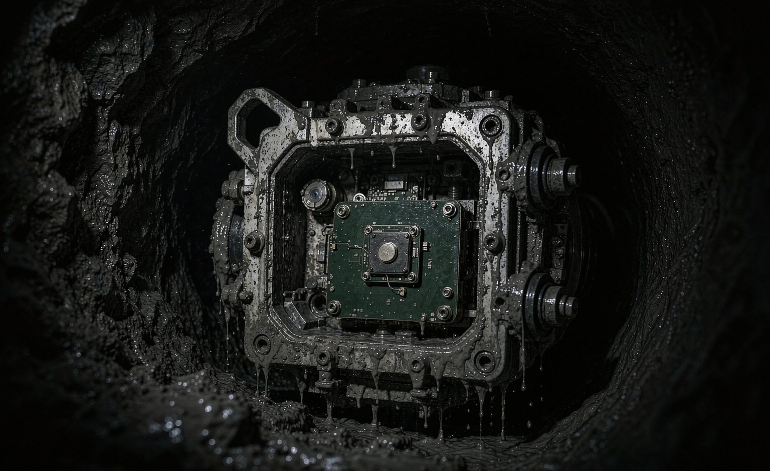
Figure 4. The operating environment is not a cleaned-up laboratory bench.
There are four things I now ask about before looking at the headline accuracy number.
1. Bias over temperature, not at 25 °C
A single room-temperature number says very little. What matters is the bias curve across the full operating range, and how well it is compensated in the sensor's actual mounting configuration.
2. Scale factor and bandwidth
Scale factor determines how accurately angular rate is converted into a digital value. Bandwidth determines whether the sensor tracks real tool motion without amplifying structural vibration into the attitude solution.
3. Mounting alignment
If the gyro axes are not aligned with the tool coordinate frame, that offset becomes a systematic error. No amount of filtering removes it. Repeatable mechanical mounting and proper calibration matter as much as the sensor itself.
4. Sensor fusion
The gyro, accelerometers and any auxiliary measurements have to work together. In a vibrating drill string, the fusion algorithm is what turns raw inertial data into a usable tool-face estimate.
The silicon die is the starting point. What makes it useful downhole is everything built around it: thermal characterisation, isolation, calibration and fusion.
A practical selection checklist
Ask for bias stability across temperature, not only at ambient.
Request the shock and vibration test profile, including resonance behaviour.
Check how installation error is calibrated and whether it is repeatable between runs.
Review the fusion architecture: how gyro, accelerometer and survey data are combined.
Confirm output latency and update rate against the steering workflow.
Understand the failure modes. A sensor that fails quietly is worse than one that fails obviously.
These questions are not about chasing the highest specification. They are about whether the measurement stays trustworthy after the tool has been run in a real well. That is the difference between a component that works on a bench and a system that works downhole.
MEMS gyros will not replace every high-grade gyroscope. But in the space where downhole tools actually live - small, hot, vibrating and cost-constrained - they have become a genuinely practical way to know which way the bit is pointing.