
AT A GLANCE
|
Earth rotates at 15 °/h - a reference that costs nothing, never stops and cannot be forged. A consumer-grade MEMS gyro carries bias and noise of the same order, so the signal has to be dug out of the error. To do that, the device's own error must sit roughly two orders of magnitude below the signal: mechanics, electronics and calibration, all at once. That is the entry ticket to gyrocompassing - and the reason MEMS now holds its own downhole, where magnetics and GNSS both fail. |
1. Start with one number: 15 °/h
Earth completes one revolution every 24 hours. At any point on the surface, that works out to an angular rate of 15 degrees per hour - 0.0042 degrees per second. It is a quiet, constant signal that never stops.
Now run a thought experiment. Leave a phone flat on the desk, open the gyroscope readout and watch the numbers. A consumer-grade gyro at rest typically wanders by a few degrees per hour, sometimes ten or more, from bias and noise alone. In other words, the Earth-rate signal is about the same size as the error of an inexpensive gyroscope.
Recovering the signal from that error requires the device's own error to be smaller than the signal by roughly two orders of magnitude. That gap - an error of 0.1 °/h or better against a 15 °/h signal - is the whole difficulty of the problem. Figure 1 sets the requirement against the gyroscope classes available today.
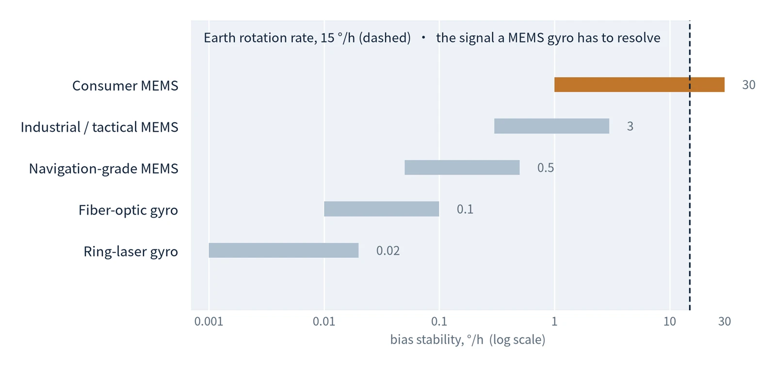
Figure 1 · Bias stability by gyroscope class, against the 15 °/h Earth-rate signal
Order-of-magnitude illustration based on typical published specifications; individual products vary by an order of magnitude or more. Source: compiled by the authors.
2. Why this number decides whether a gyro can find north
Earth's rotation is a direction reference that costs nothing, never switches off and cannot be jammed or forged.
A magnetic compass works from the geomagnetic field: inexpensive, convenient and corruptible. A steel tool, a power cable, a casing string, a nearby well - any of them can pull the needle away from true north. Earth's rotation is influenced by none of it. A gyroscope that can reliably resolve 15 °/h, combined with the gravity vector for levelling, can compute north on its own - without GNSS and without a trustworthy magnetic field. This is the principle of gyrocompassing, and the starting point of every high-grade inertial heading system.
Read that way, "can it measure 15 °/h?" is not a datasheet question. It is the qualification test for independent north-finding.
3. How a vibrating chip senses rotation
A MEMS gyroscope has no flywheel and no bearings. Its core is a proof mass, driven electrostatically, oscillating back and forth on a silicon die at a few kilohertz.
The physics fits in a single sentence: the mass is vibrating, the die is rotating, and the two together produce a lateral force - the Coriolis force. Its magnitude is proportional to the input rate, its direction is perpendicular to the drive velocity, and it is read out as a differential change in capacitance on the sense axis. No rotation, no force; faster rotation, larger force. Because the force alternates with the drive frequency, the sense signal appears as a modulation that can be demodulated synchronously - which is how a displacement of a few nanometres becomes a rate reading (Figure 2).
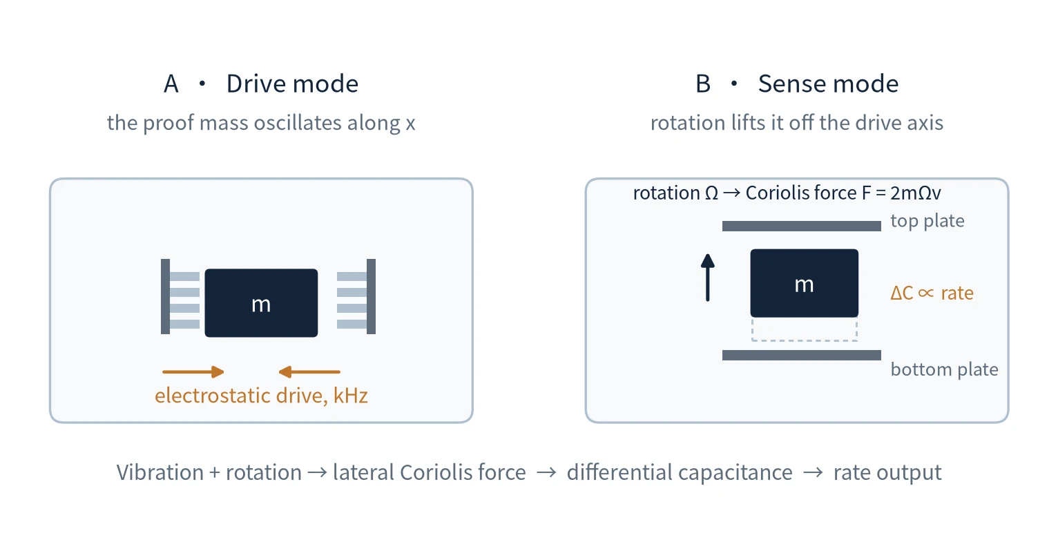
Figure 2 · Drive and sense modes of a tuning-fork MEMS gyroscope (schematic)
4. The hard part: recovering a sub-nanometre signal
How small is the Coriolis force at 15 °/h? The displacement it produces is measured in nanometres, sometimes less than one, and it is buried in thermal noise. Reading it is not a matter of a single clever trick; it is three disciplines executed at the same time - and Figure 3 shows how they divide the error budget.
Mechanical design. A high-Q resonant structure keeps the drive oscillation stable and spectrally pure, so the signal rises clear of the noise floor instead of dissolving into it.
Interface electronics. The front end must resolve a picofarad-level capacitance change while contributing almost no noise of its own. In many designs it is the circuit, not the silicon, that sets the limit.
Error modelling. What remains - temperature drift and non-linearity - is removed by factory calibration and by compensation running on the device.
|
"Miss any one of the three, and 15 °/h is nothing but noise." |
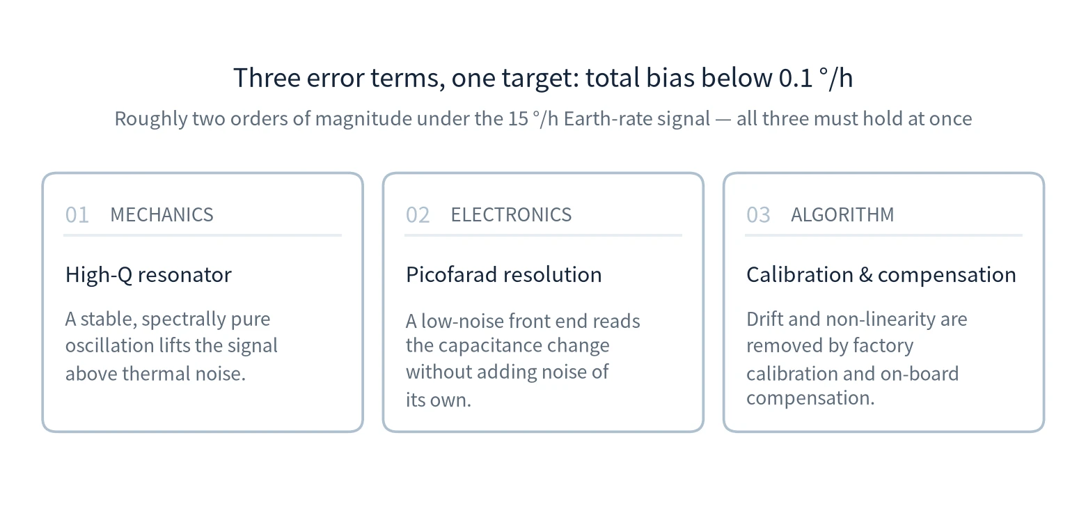
Figure 3 · The three error terms that must be held below 0.1 °/h simultaneously
5. Between consumer grade and navigation grade
Both are built with the same MEMS process. The difference is not the principle; it is what you are prepared to pay for.
A handset gyro costs a few dollars and is allowed a large error, because its job is to rotate a screen or steer a game; a few degrees off is invisible. A navigation-grade device adds structural design, vacuum packaging, thermal control and multi-point calibration, layer on layer, and its cost rises by orders of magnitude. In between sits the quasi-navigation tier that process maturity has pushed downmarket over the past few years - the band that industrial work such as downhole surveying can actually afford. Table 1 compares the grades side by side.
Put bluntly: it is not that MEMS cannot measure 15 °/h. It is that a three-dollar MEMS has no reason to.
|
Class |
Typical bias stability (°/h) |
Relative cost |
Typical role |
|
Consumer MEMS |
1 – 30 |
$ |
Screen orientation, gaming, dead reckoning |
|
Industrial / tactical MEMS |
0.3 – 3 |
$$ |
Stabilisation, tilt/azimuth, borehole survey |
|
Navigation-grade MEMS |
0.05 – 0.5 |
$$$ |
North-finding, short-range navigation |
|
Fiber-optic / ring-laser gyro |
0.001 – 0.1 |
$$$$ |
Long-duration navigation, geodesy |
Table 1 · Grade comparison for MEMS and optical gyroscopes
Indicative ranges; relative cost is a qualitative indicator, not a price list.
6. Why the effort pays: downhole there is no second option
Return to the application that motivates this discussion: directional surveying in oil and gas wells. Borehole orientation has traditionally come from magnetometers reading the geomagnetic field. At several thousand metres, that approach frequently fails. Casing, offset well strings and magnetised drill collars all distort the field, and the more valuable the operation, the less reliable magnetics become - window milling through casing, relief wells, re-surveys of ageing wells. Downhole there is no GNSS either.
A gyroscope that finds north on its own is the remaining option. Compared with a fibre-optic gyro, a MEMS device offers a smaller envelope, better shock tolerance, lower power draw and controllable cost. The price is having to deliver the 15 °/h performance in a far harsher environment (Figure 4).
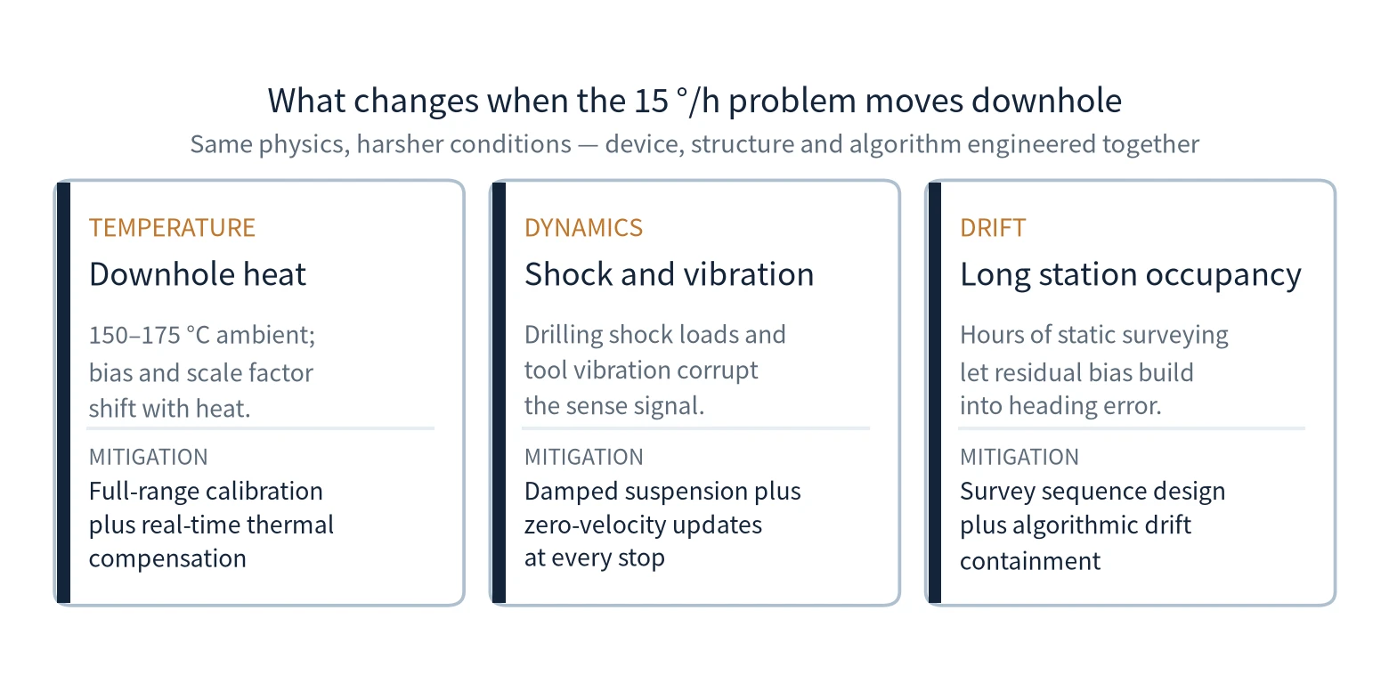
Figure 4 · The three engineering constraints a downhole MEMS gyroscope has to survive
Typical high-pressure, high-temperature logging conditions; confirm limits against tool specifications.
Heat is contained by full-temperature calibration and real-time compensation, vibration by damping structures and zero-velocity updates, and long-term drift by survey design and algorithmic containment. Device, structure and algorithm have to be developed along the same line before a MEMS gyroscope genuinely holds its ground downhole.
7. In summary
Three statements answer the question in the title.
|
PHYSICS |
A vibrating proof mass converts rotation into a measurable Coriolis force. |
|
ENGINEERING |
Resonator, electronics and calibration together hold the error two orders of magnitude below the Earth-rate signal. |
|
APPLICATION |
Those 15 °/h buy an autonomous heading reference that depends on neither a magnetic field nor a satellite - credible pointing in the blind zones: downhole, in tunnels, indoors. |
A better gyroscope is not an end in itself. It is what allows a survey to be trusted in places where nothing else can be trusted.